Learn how to build a prototype that utilizes the native device motion sensors. In this lesson we are going to use the device’s accelerometer to view a panorama photo as we tilt the device.
We will walkthrough the Device Motion patch to understand how to use data from the device sensors to affect properties like position.
Download the tutorial starter file to follow along as we rebuild this prototype.
Getting Started
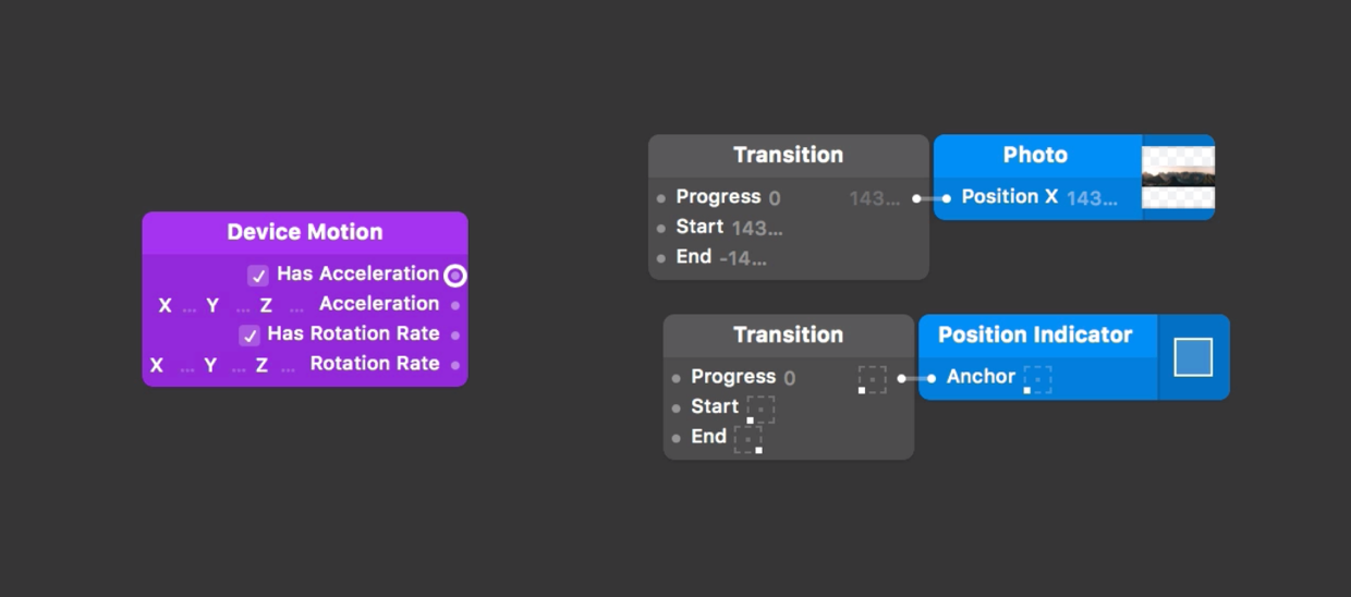
The tutorial starter file contains a photo layer and a group that contains the photo’s description and a scroll bar. The photo is a panorama, so only a portion will be displayed when filled to the screen height.
To view the rest of the photo, we can pan horizontally by changing the X position. We have two Transition patches already setup in the Starter file, the first Transition patch changes the photo layer’s X position to reach the left and right edges. The second Transition patch moves the anchor point of the scroll bar from the left to the right corner.
Mirroring your prototype on Origami Live
To pan the photo as the device tilts, we’ll need to use the motion data from a connected device. Connect a device to your computer and open the Origami Live app, if connected successfully a live preview will display on device. If not, read the ‘Live Preview on a Device’ section of the Previewing and Sharing tutorial to get started.
Using Device Motion
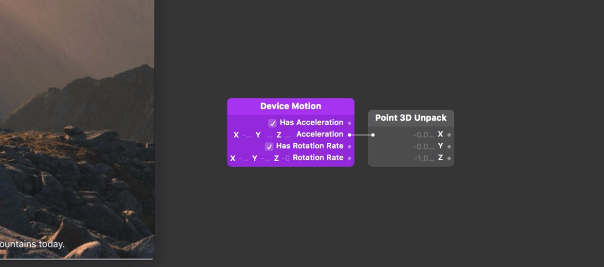
Now that we have connected a device, lets access the motion data from the device’s sensors. Do this by inserting a Device Motion patch to the Patch Editor. You’ll notice this patch has outputs from two different device sensors: the Accelerometer (Acceleration) and the Gyroscope (Rotation).
The accelerometer measures increments of gravitational acceleration in 3 axes. Acceleration values may be positive or negative depending on the direction of the acceleration. For example if we tilt the phone to the right, the X-axis acceleration will increase and if we tilt to the right the value will decrease.
The gyroscope measures the rates at which a device rotates around 3 axes. If we rotate the phone to the side, the rotation rate will increase on the X-axis until we stop rotating and the device is still again. The quicker we rotate the device, the greater the rotation rate value on the X-axis.
In this prototype we want to move the photo from left to right dependent on the devices tilt. To do this we will use acceleration on the X-axis.
The Acceleration output on the Device Motion patch is a 3D Point value, which is combined set of 3 numbers. Since we’ll only need to use the X value, we’ll use a Point 3D Unpack patch to separate the three dimensional value into independent values. Insert a Point 3D Unpack patch to the patch editor and connect the Acceleration output from the Device Motion patch to the input on the Point 3D Unpack patch.
Smoothing the acceleration value
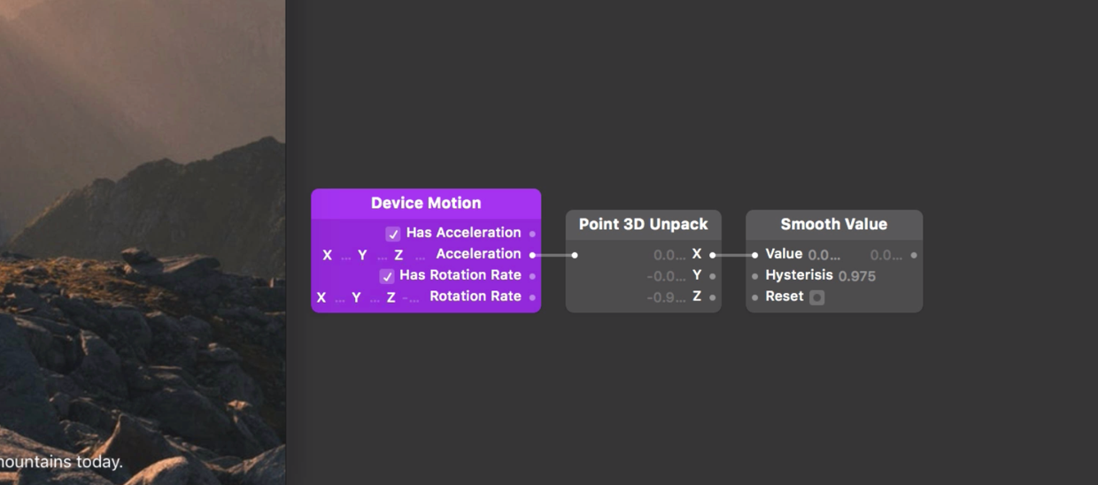
You will notice by looking at the Point 3D Unpack patch that the acceleration value on the X-axis is unsteady. This is due to the high sensitivity of the sensors, to level this out we can use the Smooth Value patch. Insert a Smooth Value patch to the patch editor. Connect the X output from the Point 3D Unpack patch to the input on the Smooth Value patch.
The output value on the right hand side of the Smooth Value patch still has some background noise. We can increase the hysterisis value to increase the amount the input is smoothed. Let’s increase this from 0.4 to 0.975. Now we can see that whilst the output is hardly effected by background noise, the value changes smoothly as we tilt the device.
Creating a feedback loop
This X acceleration value represents the current orientation of the device. If we connected this directly to our transitions, the position of the photo would match the tilt of the phone. We would have to tilt the device 90 degrees to the left to move the photo to the far left position. Instead we want the the photo to drift to the left as long as we tilt the device, speeding up the more the device is tilted.
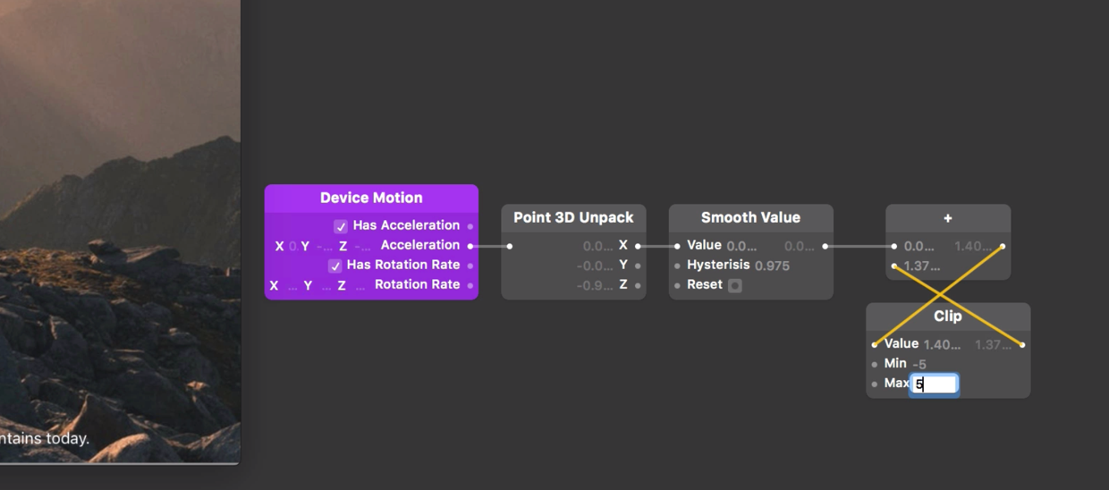
To do this, we need to accumulate all of the acceleration values over time. This process is called creating a feedback loop. To start, insert an Addition patch to the patch editor. Connect the output from the Smooth Value patch to the first input on the Addition patch.
To create the feedback loop, we need to pass the output from the Additionpatch back into itself. Origami Studio doesn’t allow an output of a patch to be connected to an input of the same patch, so we need to place another patch in the middle. We’re going to use the Clip patch, so we can set the bounds of how much we accumulate the acceleration values, otherwise the photo will tilt indefinitely.
Insert a Clip patch to the patch editor. Connect the output from the Additionpatch to the input on the Clip patch. Now connect the output from the Clip patch to the second input on the Addition patch.
Our feedback loop has been created, but we need to define accumulation bounds. The bounds need to be big enough so the photo doesn’t tilt to the far left or right too quickly, but not too big that it takes too long to reach the far edges. Set the Min input on the Clip patch to -5 and the Max input to 5.
We can test these limits by tilting the phone from left to right and checking the output of the Clip patch doesn’t reach our minimum or maximum bounds too quickly.
Progress & Transitions
All that’s left is to connect the accumulated acceleration value to our two Transition. The Transition patch converts a progress value of 0 to 1 into a custom range, as defined by its start and end value. Our accumulated acceleration can be a value in a range of -5 and 5, so we need to normalize this value into a 0 to 1 progress range.
Insert a Progress patch to the patch editor. Connect the output from the Clip patch to the Value input on the Progress patch. Set the Start Value input to -5 and the End Value input to 5.
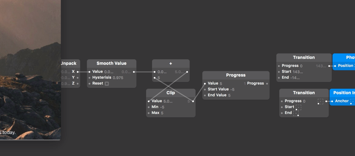
Finally, connect the output from the Progress patch to the Progress inputs on both Transition patches.
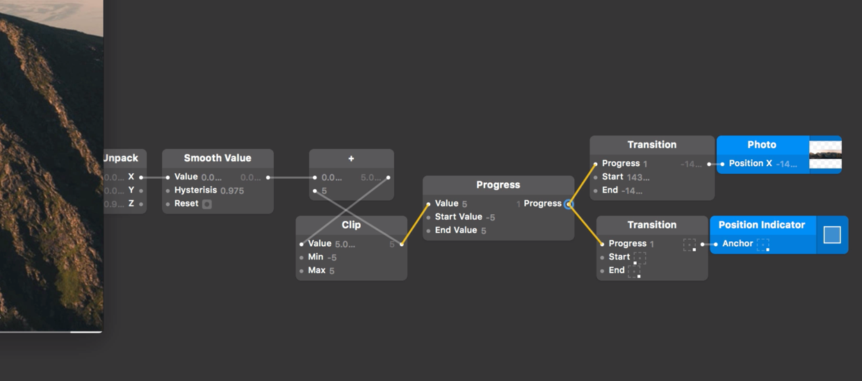
Now as we tilt the device from left to right and the accumulated acceleration moves between -5 and 5, the Progress patch moves between 0 and 1 and the Transition patches are progressed to move the photo and scroll bar.
Wrapping Up
We have now setup our prototype to respond to device motion, understood the difference between device acceleration and rotation rate and linked this data to transitions in our prototype using a feedback loop.